LINKING P&ID DIAGRAMS WITH 3D MODELS FOR ERROR-FREE AND EFFICIENT EXECUTION
3D modeling of industrial plants with technical consistency and precision
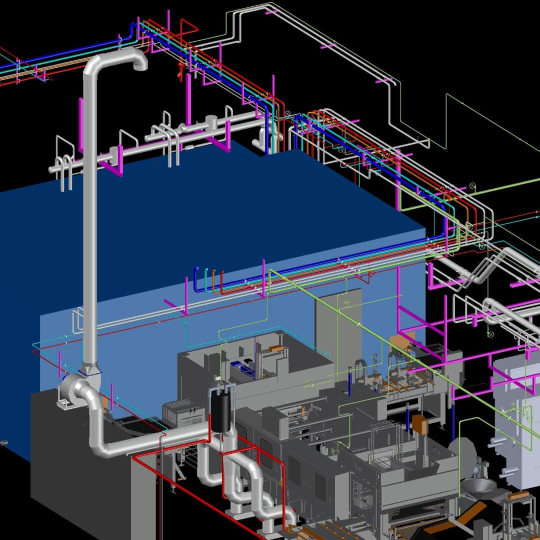
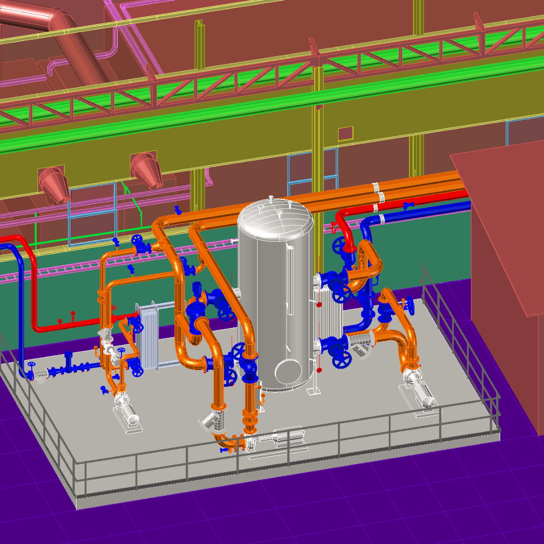
All system elements – from piping to equipment and fittings – are aligned through a central model, enabling accurate isometrics, automatic specifications, and better project execution.

CHALLENGES
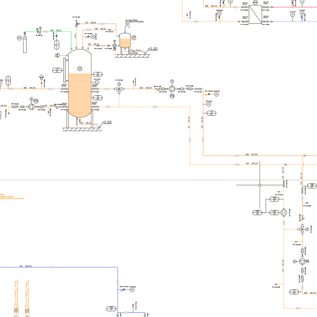
A need to integrate P&ID and 3D models
To prevent inconsistencies and errors in later construction phases.
Accurate specification of materials and equipment
For optimal procurement, planning, and precise budgeting without unexpected costs.
Need for optimized design of supports and pipe hangers
To ensure better static and spatial alignment of the system.
ADVANTAGES OF OUR APPROACH
Faster and more accurate design
Automatic tracking of all changes in the model and documentation.
Fewer changes on-site
Designed solutions are verified before construction begins.
Improved team coordination
All stakeholders work from a single, unified data source.
Clash elimination in projects
Visual and technical checks performed before construction.
More efficient procurement and planning
Automated bills of quantities and accurate material specifications.


START YOUR PROJECT
We use AutoCAD Plant 3D and P&ID to link technical diagrams with 3D plant models, enabling automatic synchronization of all changes. This accelerates decision-making and ensures consistency across all project documentation.
